

Published by Security Testing and Assurance on 13 June
Summary
This article serves as a beginner’s hardware hacking journey, performing a BIOS password bypass on Lenovo laptops. We identify what the problem is, how to identify a vulnerable chip, how to bypass a vulnerable chip, and finally, analyse why this attack works and ways that it can be prevented.
What is the problem?
In rolling out new consultant laptops at CyberCX, several Lenovo laptops were retired from primary business use. The process involves wiping each device and deciding if the hardware still operates correctly. If the hardware is still workable, then it can be added to the pool of available devices for research or specific jobs that require an additional laptop. However, in this instance, most of our internal team had conveniently forgotten their BIOS passwords. BIOS passwords are designed to prevent unauthorized access to the hardware systems and their configuration. However, when these passwords are forgotten or misplaced, it can mean the inability to perform device wiping or hardware changes.
If you have not already, I would highly recommend including capturing BIOS passwords as part of the laptop setup process (it is in ours now).
As we did not want to waste the hardware, I started investigating how to get around the BIOS password for these Lenovo laptops.
It should be an easy fix, right?
An old approach to resetting the BIOS would be to remove the coin cell battery and wait 5-10 minutes. This resets the BIOS configuration to factory defaults. This may have worked previously; however, on modern systems the configuration is stored in non-volatile storage on the motherboard. A different approach would need to be taken with these laptops.
A vulnerability identified with the BIOS of these laptops is that the Electrically Erasable Programmable Read-Only Memory (EEPROM) is separate from the BIOS chip itself. This means that if we can intercept or interrupt this communication, then the prompt for a BIOS password may be bypassed. This vulnerability is publicly well known; the best writeup I have found is an article by David Zou (Zou, 2016). My research intends to build on this work in order to allow CyberCX to repurpose these retired laptops.
How to Identify Vulnerable Chips?
As mentioned previously, the Lenovo laptops that were being retired have a separate BIOS chip to where the BIOS settings are stored. This setup is not unique to Lenovo as other manufacturers have the same implementation problem.
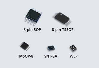
For Lenovo laptop motherboards, the EEPROM is an 8-Pin Thin Shrink Small Outline Package (TSSOP). This can come in several configurations, as shown in Figure 1.

Figure 1 ABLIC Inc. (Eeprom_fig051, 2013)
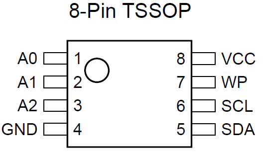
Looking carefully at each chip on the laptop motherboard allows us to identify several SOP, TSSOP, and TMSOP-8 packages. The way that the EEPROM communicates is over the Inter-Integrated Circuit (I2C or I2C) protocol. The pinout diagram shown below (Figure 2) is for the TSSOP, however the pinout remains the same for each of the EEPROM packages.
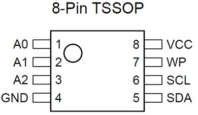
Figure 2 Zou, D. (8pinEEPROM, 2016)
Using this information we will identify the BIOS EEPROM on a Lenovo laptop, then perform an attack against the Serial Clock (SCL) and Serial Data (SDA) pins to modify or interrupt the communication.
How to Bypass BIOS Password?
The volunteer in this instance is a Lenovo L440, as shown already torn down in Figure 3.
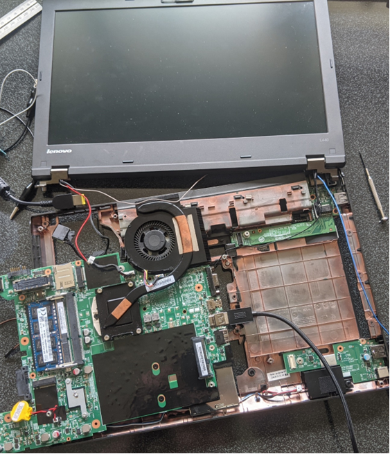
Figure 3 Lenovo L440 Laptop Target
To perform a successful attack against the BIOS password of this laptop the following process will be followed:
- Locate the correct EEPROM chip.
- Locate the SCL and SDA pins.
- Short the SCL and SDA pins at the right time.
On the Lenovo L440 there were three chips that kind of fit the package and pinout criteria we are looking for.
The easiest way to identify if the chip is a candidate is to search for the serial number and the word EEPROM. Often it will be quickly obvious if the chip is or is not an EEPROM based off the search results. However, it should be noted that many manufacturers do not put the actual serial number in place. They all have their own standards and versioning systems, which can make the process of identifying components difficult. The following figures show three candidates identified on the Lenovo L440 that could be the EEPROM we are looking for.
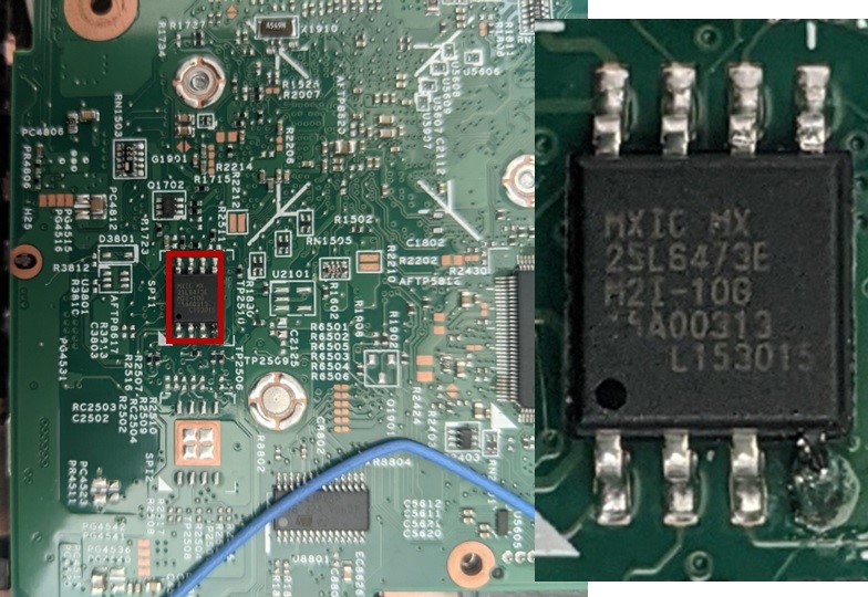
Figure 4 Possible Candidate #1 An 8-Pin SOP
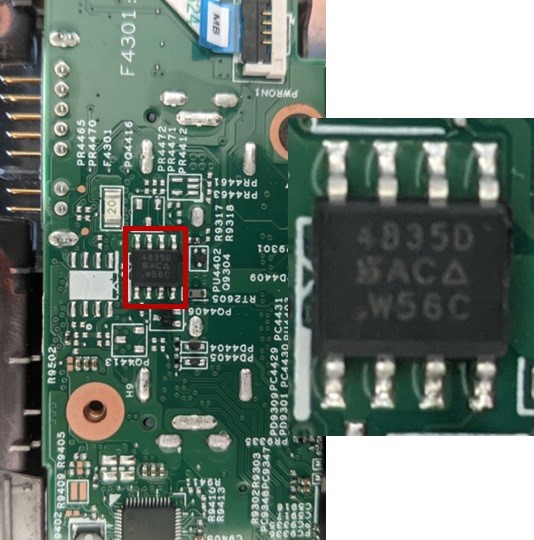
Figure 5 Possible Candidate #2 An 8-Pin TSSOP
Figure 6 Possible Candidate #3 An 8-pin TMSOP
The first candidate (Figure 4) has the serial MXIC MX 25L6473E, which appears to be a 64 MB Flash CMOS. So, while part of the BIOS, is not the chip we are looking for.
The second candidate (Figure 5) has the serial 4835D AC W56C, which appears to be a metal–oxide–semiconductor field-effect transistor (MOSFET) of some sort. Useful for power delivery and smoothing but not for storing data.
The third candidate (Figure 6) has the serial L08-1 XH and appears to be the EEPROM we are looking for. This is where the configuration is stored by the BIOS.
For those looking close enough, I did originally perform this attack against the wrong chip. The ground pin of the 64 MB Flash CMOS was the unlucky victim in the process, the laptop still powers on and works, though.
A quick demo of the attack working is shown below, this is performed on a Lenovo X230, but the same attack process still applies.
I identified the EEPROM as shown in the top right. I can get into guest mode of the BIOS without knowing the password, but no changes can be made.
Remember, we are interested in the SCL and SDA pins. All we will need to do is short these at the correct time and they will bypass the password prompt.
As you can see in the demo, I power the laptop on, then I use the ‘elite’ technique of jamming a small screwdriver across the SCL and SDA pins to short them until entering the BIOS.
An interesting note is you could bypass the password, make changes to the BIOS, for example change the boot drive, and then not perform the short on next boot. You could then load into a new OS, do what you need to do, then re-short the pins again, changing the setting back. This still leaves the existing password in the EEPROM so a victim’s laptop would not have any evidence of tampering.
Why does this attack work?
Let us dig further into why this attack works. The first thing to do is to hook up the SCL and SDA pins to an oscilloscope. The model I used is shown in Figure 7.
Figure 7 Siglent SDS 1202X-E Oscilloscope
The first attempt at connecting the EEPROM chip failed as the smallest TSSOP 8-pin clip that we had in the workshop was too big (indicating that this is either a smaller version, or a TMSOP). This issue is shown in Figure 8.
Figure 8 8-pin TSSOP Clip
However, our workshop has acquired a PCBite set that allows probing the tiniest of pins on a board. Figure 9 shows just how small these “legs” are of the EEPROM.
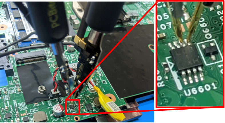
Figure 9 PCBite Pins attached to the EEPROM.
Figure 10 shows the pinout mapped to the EEPROM on the motherboard.
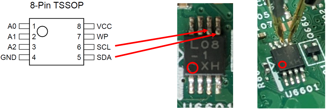
Figure 10 Showing the pin layout of the identified chip.
With the correct pins now hooked up to the oscilloscope, we can attempt to view the communication between the BIOS and the EEPROM when booting.
It had been a very long time since I had used an oscilloscope; I found the following from Siglent to be useful for getting the correct configuration. Additionally, the model of oscilloscope we have in the workshop supposedly comes with automatic serial communication decoding!
These two videos from Siglent and MyVanitar helped setup and understand how to configure each setting to be able to read the correct information.
(Siglent Technologies, 2017) https://www.youtube.com/watch?v=mXJN7FwpKHg
(MyVanitar, 2020) https://www.youtube.com/watch?v=yzcia8C-Y7Y
Additionally, the following specifications are from a Mouser datasheet that match the EEPROM chip we are attacking.
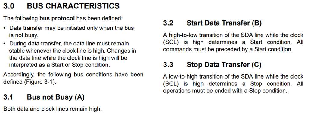
Figure 11 Snippet from Microchip (2003) Datasheet
The Bus Characteristics description includes the following definition for the communication protocol which can explain our attack. “Data transfer may be initiated only when the bus is not busy” (Microchip, 2003). Along with the Bus not Busy definition, “Both data and clock lines remain high” (Microchip, 2003).
Additionally, the datasheet provides a visual representation of the communication protocol. The start and stop mechanism: the BIOS would perform a start command, send the data, then send a stop signal to signify the end of communication.
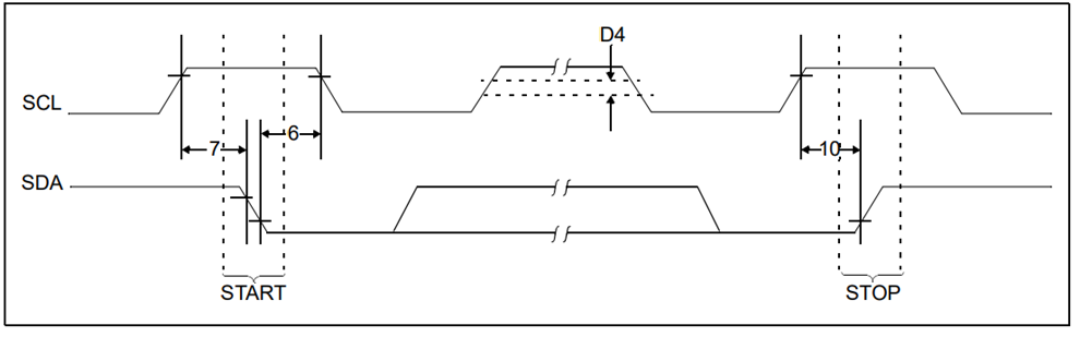
Figure 12 Start/Stop (Microchip, 2003)
What should be noted here is that the BIOS requires the start signal or the laptop will not boot. This is why we cannot just short the pins before turning the laptop on.
Looking at the output of our fancy oscilloscope in the following figure, we can see that the start signal is sent approximately 5.32 microseconds after the power button has been pressed. It should be noted that for the oscilloscope readings, the yellow line is SCL (Clock), and the purple line is SDA (Data) unless stated otherwise.
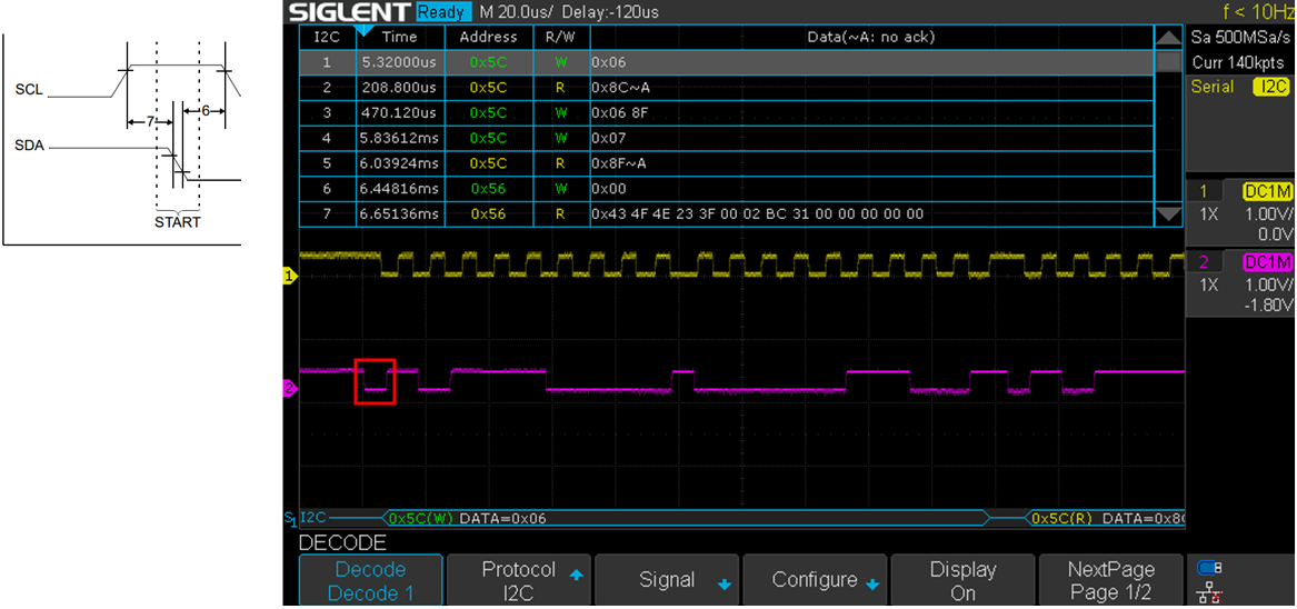
Figure 13 Output of oscilloscope showing start signal.
From Figure 13 we can see the start condition happening and then the first 0x06 DATA Write operation. Notice the time difference here: 5.3 microseconds from power on, the first operation happens, then a read and write, then nothing until about 6 milliseconds after the power has been turned on.
This initial power on appears to be the BIOS performing a check on the EEPROM. As discussed earlier, this check must happen, otherwise the BIOS will prevent the system from booting any further. This prevents us from shorting the EEPROM pins before the power is applied.
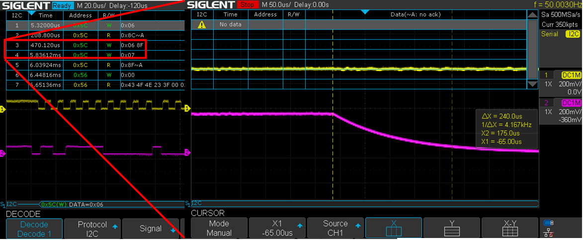
Figure 14 Oscilloscope View when pins are shorted.
Figure 14 shows the view on the oscilloscope once I short the SCL and SDA pins. Note that the timing X axis is out by a bit between the two images. The short happens approximately between the 470 microsecond and 5.8 millisecond points. This shows SDA is low while SCL is high, which according to the protocol description indicates a busy line.
While testing this bypass, the timing for shorting the pins does not have to be quite this tight. If the pins are shorted slightly later, this still results in a successful bypass. Additionally, the password must be read by the BIOS later in the sequence as the short must remain until entering the BIOS configuration.
To add to the complexity, some BIOS use the TPM, or encrypt or hash the BIOS password. Every model, even within the same manufacturer, is different and of course this process is not documented.
In my instance, with the Lenovo laptops, I could not get the Read/Write bytes to repeat (after the Write, Read, Write startup check process). The bytes that were returned did not appear to decode into any discernible format.
If I had access to the documentation for the communication bytes, or if I read off the entire EEPROM, then it is possible that I may have been able to grab the BIOS password in plaintext.
![]()
Figure 15 Example of captured Bytes being read from the EEPROM.
I am almost certain that it is possible to read the data from the EEPROM, possibly I have hooked up something wrong, or used the wrong decoding. We will have to leave that for future research. For now, the bypass works consistently, and we now have a fairly good understanding of why this vulnerability exists.
How can this be prevented?
When attempting to model this particular threat, it is important to keep in mind that this requires complete physical access for possibly a minimum of a few hours. Additionally, the use of full disk encryption (with a Passphrase and TPM) would prevent an attacker from obtaining data from the laptop’s drive.
In order to increase the difficulty of this type of attack, manufacturers could include the BIOS and EEPROM packages into one Surface Mount Device (SMD). This would require performing a chip-off attack to intercept the same communications. Some motherboard manufacturers already use this process, either on purpose or unintentionally, for modern or higher-end systems.
References
- ABLIC Inc. (2013). Eeprom_fig051 [Photograph]. https://www.ablic.com/en/semicon/wp-content/uploads/2013/02/eeprom_fig051.jpg
- Microchip (2003, July 28). 24AA08/24LC08B 8K I2C™ Serial EEPROM. Mouser. https://www.mouser.com/datasheet/2/268/21710c-76077.pdf
- Zou, D. (2016, March 28). BIOS Password Bypass. Davidzou.com. Retrieved May 23, 2023, from https://davidzou.com/articles/bios-password-bypass
- Zou, D. (2016). 8pinEEPROM [Photograph]. https://davidzou.com/user/pages/03.articles/bios-password-bypass/8pinEEPROM.png
- [Siglent Technologies]. (2017, June 17). Troubleshooting a serial bus using a SIGLENT SDS oscilloscope [Video]. Youtube. https://www.youtube.com/watch?v=mXJN7FwpKHg
- [MyVanitar]. (2020, December 4). I2C Signal Decoding/Debugging using Siglent SDS2102X Plus and SDS1104X-E Oscilloscopes [Video]. Youtube. https://www.youtube.com/watch?v=yzcia8C-Y7Y
Author: Dajne Win – Principal Security Consultant
We are hiring! CyberCX currently have open offensive roles in penetration testing, adversary simulation, and AppSec for Australia and New Zealand. If you are interested in working with the largest and most capable team in the region in a fun, rewarding, and challenging environment, please send your CV to [email protected]


