
Ben discusses a method for gaining a root shell on the PlayStation Classic with the use of hardware hacking techniques.
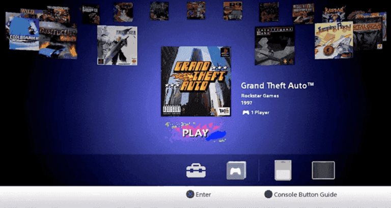
The PlayStation Classic (PSC) is a hobbyist gaming console – for the nostalgic types. It comes with a cool miniature version of the original console casing, and two controllers. Unlike modern gaming consoles, a minimal amount of effort has gone into securing the console. The PSC comes with 20 game ROMs stored on the flash, and they’re loaded into the console emulator from the retro looking UI.
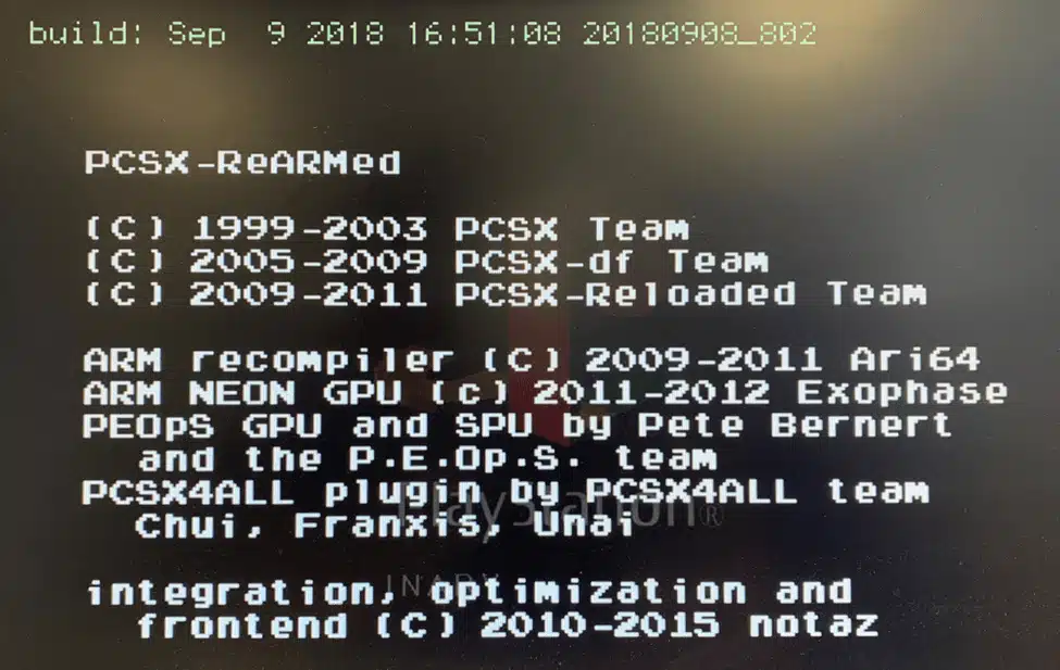
The console runs an open source emulator called PCSX-ReARMed. It is a fork for ARM processors of the PCSX-Reloaded emulator. Essentially the PSC is a Raspberry Pi with a couple of USB controllers.
Googling for “hack playstation classic”, you’ll come across projects like BleamSync and AutoBleam for loading up extra game ROMs. The bleem name is a reference to Bleem!. These projects rely on executing an arbitrary shell script on the PSC by encrypting and signing a script with GPG keys and a passphrase that is stored on the flash in /root/.gpg.
The GPG keys are stored on the flash to allow authorised update providers to run update scripts on the PSC to make changes to the file system – as the PSC has no network connectivity. The advantage of gaining command execution through USB is it’s easy for users to exploit. You just pop in a USB flash drive with a prepared script, and off you go.
However, this blog post is about hardware hacking, so we’re going to take the PSC apart instead and reflash a modified rootfs partition to give us a root shell over serial. There’s more soldering and destruction involved, but it works and the same methodology applies to other similar devices.
Debugging Interfaces
The first step to gaining visibility of how the PSC works is looking for debugging interfaces, such as Universal Asynchronous Receiver/Transmitter (UART) or Joint Test Action Group (JTAG).
There is a UART interface on the PlayStation Classic. However, output is disabled once the operating system has booted to a certain point unless the following two pins on the ‘SIDE B’ of the board are bridged together. It’s likely the pins are mapped to General Purpose Input/Output (GPIO) pins on the System on a Chip (SoC) which are being checked by boot scripts to enable/serial the serial interface.
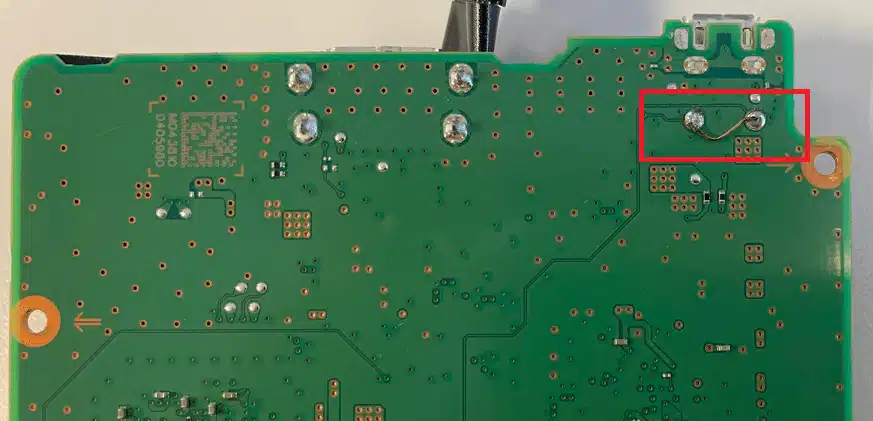
Fortunately, I didn’t need spend time working this out as the location and purpose of these pins was already publicly known, thanks to Yifan Lu.
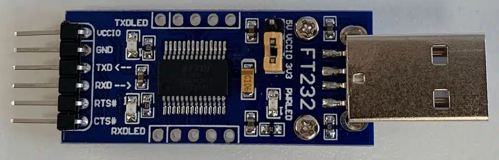
UART is an asynchronous serial communication protocol for data transmission between two devices. It uses four pins: ground (GND), transmit (TX), receive (RX) and power (VCC). A USB to TTL adapter is a valuable adapter for communicating with a target device’s UART interface and costs only a few dollars.
You’ll often find messages are output to the UART interface, or even a usable shell prompt. Unfortunately (for us) device manufacturers are now restricting UART to output messages only, password protecting logins, or using a restricted shell to limit command usage.
To actually boot the PSC, it needs to be powered by a wall socket as the operating system checks the charger type. Later on, when using fastboot, we’ll connect the PSC to a computer over USB.
The image below shows the pin layout for the UART interface (excuse my bad soldering job). When connecting to UART with a USB TTL adapter, you do not need to connect the power (VCC). The UART runs at 3.3V, which is quite common (along with 5V). However, you may see other voltages, such as 1.8V. It’s worth checking the output of the pins before connecting anything.
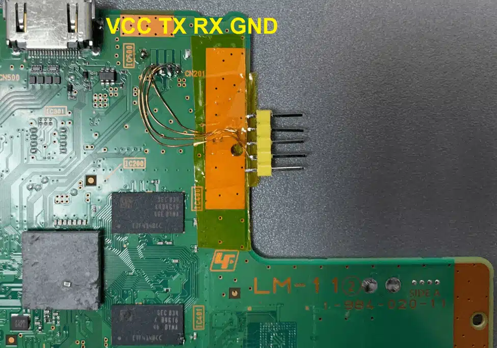
A trick to locating UART pins – is to start with the easy to find pins first, then work your way back. GND can be found with the continuity buzzer mode on a multimeter connecting the pin and a known ground point, such as the metal casing of the USB port. The next pin I’d recommend locating is TX, which will go into the RX pin on the USB TTL adapter. When you have the right baud rate and other serial settings, you should see readable data being received. RX is likely the remaining pin that isn’t VCC.
When you attach to the PSC UART interface with a USB TTL adapter, you’ll notice a login prompt. Attempting to login as root will fail, as the root user does not have a password configured. The baud rate of the UART is 921600, not the 115200 you might often see.
# picocom /dev/ttyUSB0 -b 921600
aiv8167-rockman-emmc login:
Yocto aud Baseline 11.0.1 aiv8167-rockman-emmc ttyS0
The next step is to get a full dump of the flash data, so we can find something simple to modify on the file system that will result in a usable shell.
Flash Chip-Off
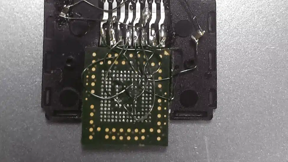
The fastest (but most destructive) method of obtaining a firmware dump is to physically remove the eMMC flash chip from the PCB. On the PSC there was nothing more than the solder on the pins holding the chip in-place, so it took just a couple of minutes of pointing a heatgun at the chip at ~360 degrees to have the chip come off. Anecdotally, it takes about 5 to 7 times of exposing a flash chip to high temperatures for it to stop working.
Once the flash chip was off, I spent a bit of time tidying up the pins. The flat end of a soldering iron tip can be useful to melt off any solder than has bridged two pins. A good clean set of pins is the best chance of a successful read.
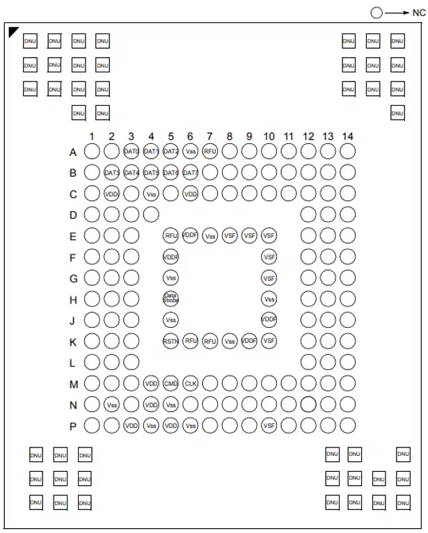
The flash chip is a Samsung KLMAG1JETD-B041 16GB eMMC with a BGA-153 pin footprint. The footprint image below shows purpose of each pin. A significant amount of the pins are unused (NC – Not Connected).
An interesting related presentation on eMMC “Hardware Hacking With A $10 SD Card Reader” was presented at BlackHat in 2017 by Amir “Zenofex” Etemadieh, CJ “cj_000” Heres, Khoa “maximus64” Hoang of exploitee.rs. Slides here, and write-up here.
I did attempt to reball the BGA and reinstate the chip onto the board, but failed – likely due to exposing the flash to too much heat. This is an interesting research area that needs some experimentation around tooling, temperature, pre-heating and timing.
Dumping the Firmware
There are a number of tools available to read eMMC chips. I went with the easy but slightly more expensive option (~$200) of a USB to eMMC socket adapter from AliExpress. The adapter came with inserts for different sizes of chip and also different BGA footprints.
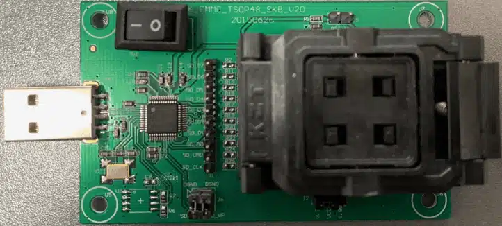
Alternatively, you could wire up each pin to an SD card. But I wouldn’t recommend it. The pins of an eMMC chip match exactly with the pins of an SD card, so convenient!
With the USB eMMC adapter, the flash will appear as a USB Mass Storage device. However, this means you won’t be able to read the BOOT0 and BOOT1 partitions, often used to store the bootloader.
The partition we’re going to modified is 7, the rootfs (200MB). The partition structure of the flash looks like this:
Disk /dev/mmcblk0: 14.6 GiB, 15634268160 bytes, 30535680 sectors
Units: sectors of 1 * 512 = 512 bytes
Sector size (logical/physical): 512 bytes / 512 bytes
I/O size (minimum/optimal): 512 bytes / 512 bytes
Disklabel type: gpt
Disk identifier: C907B807-D79F-48E2-9743-A7288A4540BA
Device Start End Sectors Size Type
/dev/mmcblk0p1 1024 17407 16384 8M Linux filesystem
/dev/mmcblk0p2 17408 33791 16384 8M Linux filesystem
/dev/mmcblk0p3 33792 34815 1024 512K Linux filesystem
/dev/mmcblk0p4 34816 35839 1024 512K Linux filesystem
/dev/mmcblk0p5 35840 39935 4096 2M Linux filesystem
/dev/mmcblk0p6 39936 44031 4096 2M Linux filesystem
/dev/mmcblk0p7 44032 453631 409600 200M Linux filesystem
/dev/mmcblk0p8 453632 535551 81920 40M Linux filesystem
/dev/mmcblk0p9 535552 29895679 29360128 14G Linux filesystem
/dev/mmcblk0p10 29895680 30535551 639872 312.4M Linux filesystem
Modifying the rootfs Partition
An easy way to gain shell access to the PlayStation Classic is to edit the /etc/shadow file to give the root user a blank password. This way the login prompt through the UART interface becomes usable.
To mount each partition as a separate loop device on Linux, I recommend running kpartx over the full disk image.
# kpartx -av psc-mmcblk0.bin
add map loop16p1 (253:0): 0 16384 linear 7:16 1024
add map loop16p2 (253:1): 0 16384 linear 7:16 17408
add map loop16p3 (253:2): 0 1024 linear 7:16 33792
add map loop16p4 (253:3): 0 1024 linear 7:16 34816
add map loop16p5 (253:4): 0 4096 linear 7:16 35840
add map loop16p6 (253:5): 0 4096 linear 7:16 39936
add map loop16p7 (253:6): 0 409600 linear 7:16 44032
add map loop16p8 (253:7): 0 81920 linear 7:16 453632
add map loop16p9 (253:8): 0 29360128 linear 7:16 535552
add map loop16p10 (253:9): 0 639872 linear 7:16 29895680
With the partitions mapped, use dd to create an image of the individual partition 7 (rootfs1).
# dd if=/dev/mapper/loop12p7 of=rootfs1.img
409600+0 records in
409600+0 records out
209715200 bytes (210 MB, 200 MiB) copied, 1.22472 s, 171 MB/s
Mount the disk image in Linux. Because the partition is ext4 formatted, there is nothing fancy required to mount it on Linux.
# mount rootfs1.img /mnt/Enable login as the root user by removing the * in the password field of /etc/shadow for the root user.
root:*:17783:0:99999:7:::
to
root::17783:0:99999:7:::
Unmount the modified disk image.
# umount /mnt
Write the Modified rootfs Partition with Fastboot
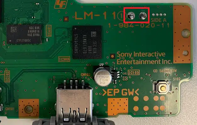
The PlayStation Classic can be booted into fastboot by bridging the two pins below on the ‘SIDE A’ of the PCB. The pins don’t need to be constantly bridged, so I recommend using tweezers to connect the pins on boot to drop into fastboot mode.
Connect the PSC micro-USB to the USB on a computer. This will power the PSC and allow communication over fastboot. Boot into fastboot mode, you’ll see the following output through the UART interface:
[eMMC] Size: 14910 MB, Max.Speed: 200000 kHz, blklen(512), nblks(30535680), ro(0)

starting app fitboot

block devices:

mmc0, size 15634268160, bsize 512, ref 11, label <null> (no erase geometry)

mmc0p1, size 8388608, bsize 512, ref 2, label BOOTIMG1 (no erase geometry)

mmc0p2, size 8388608, bsize 512, ref 2, label BOOTIMG2 (no erase geometry)

mmc0p3, size 524288, bsize 512, ref 2, label SEC_RO (no erase geometry)

mmc0p4, size 524288, bsize 512, ref 2, label MISC (no erase geometry)

mmc0p5, size 2097152, bsize 512, ref 2, label TEE1 (no erase geometry)

mmc0p6, size 2097152, bsize 512, ref 2, label TEE2 (no erase geometry)

mmc0p7, size 209715200, bsize 512, ref 2, label ROOTFS1 (no erase geometry)

mmc0p8, size 41943040, bsize 512, ref 2, label ROOTFS2 (no erase geometry)

mmc0p9, size 15032385536, bsize 512, ref 2, label GAADATA (no erase geometry)

mmc0p10, size 327614464, bsize 512, ref 2, label USRDATA (no erase geometry)

mmc0boot0, size 4194304, bsize 512, ref 1, label <null> (no erase geometry)

mmc0boot1, size 4194304, bsize 512, ref 1, label <null> (no erase geometry)

mmc0rpmb, size 4194304, bsize 512, ref 2, label <null> (no erase geometry)

fastboot_init()

[USB] udc_start_cond

MT_USB0_IRQ_ID: 104
Check the computer detected the fastboot device (a creative serial number from MediaTek).
$ dmesg
[23603.687867] usb 3-4.1: new high-speed USB device number 12 using xhci_hcd
[23604.077360] usb 3-4.1: New USB device found, idVendor=0bb4, idProduct=0c01, bcdDevice= 1.00
[23604.077362] usb 3-4.1: New USB device strings: Mfr=1, Product=2, SerialNumber=3
[23604.077363] usb 3-4.1: Product: Yocto
[23604.077364] usb 3-4.1: Manufacturer: MediaTek
[23604.077364] usb 3-4.1: SerialNumber: 0123456789ABCDEF
$ fastboot devices -l
0123456789ABCDEF fastboot usb:3-4.1
Flash the modified image to the ROOTFS1 partition on the flash.
$ fastboot flash ROOTFS1 rootfs1.img
target reported max download size of 67108864 bytes
Invalid sparse file format at header magic
sending sparse ‘ROOTFS1’ 1/3 (57508 KB)…
OKAY [ 3.037s]
writing ‘ROOTFS1’ 1/3…
OKAY [ 1.276s]
sending sparse ‘ROOTFS1’ 2/3 (63985 KB)…
OKAY [ 3.703s]
writing ‘ROOTFS1’ 2/3…
OKAY [ 1.478s]
sending sparse ‘ROOTFS1’ 3/3 (9704 KB)…
OKAY [ 0.569s]
writing ‘ROOTFS1’ 3/3…
OKAY [ 0.248s]
finished. total time: 10.312s
Once fastboot has finished writing the image, it’s safe to reboot, and now hopefully root can login.
Shell
From the UART interface login as root with a blank password. You now have shell access! From here, you could load up more game ROMs, make changes to the underlying operating system or run other emulator software.
Linux aiv8167-rockman-emmc 4.4.22 #1 SMP PREEMPT Sun Sep 9 15:21:14 UTC 2018 armv7l GNU/Linux
If you’re finding the dmesg output to be a bit of a nuisance, you can silence it by running # dmesg -n1 in the shell.
PCSX-ReARMed Settings
Normally the PCSX-ReARMed emulator menu isn’t accessible on the PSC as none of the buttons on the controller or console are mapped to the ‘Enter Menu’ option. It seems some internet people had luck inserting a keyboard into the PSC and hitting the ESC key to load the menu, however this didn’t work for me.
If you want to modify the emulator settings, you can modify the key bindings to enable the menu. These settings are per-game, as the Sony UI launcher itself just runs the emulator software. For example, Cool Boarders is game ‘2’ on the file system. Editing its key bindings allows the menu to be loaded whenever the game is running.
root@aiv8167-rockman-emmc:/gaadata/2# cat pcsx.cfg
…
bind eject = CD Change button
…
Change the binding for eject (CD change button) to load the emulator menu options.
bind eject = Enter Menu
Load up the game and tap the “change CD” button the PSC case. The emulator menu should appear, giving you access to all of the emulator settings.
Hardware Hacking Meetups
I organise a hardware hacking meetup group for Wellington, NZ locals. There are monthly meetups for anyone interested in hacking hardware and finding security vulnerabilities. In addition to the meetups, there is a Slack channel for hardware hacking discussion, which is open to people outside the Wellington, NZ region.
If you are interested in attending the meetups or chatting about hardware hacking, check out the site hardwarehacking.nz, sign-up for the mailing list or request Slack access.